Aspiración Central Allegro / Instrucciones de Instalación
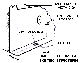
How to install Central Vacuum System STEP 1: Installing Inlet Valves STEP 2: Installation of Tube System (New or Existing Home) STEP 3: Installation of Power Unit (Machine) WARNING: Electric Shock Could Occur if Used On Wet Surfaces. STEP 1: Installing Inlet Valves a. Wall Valves in existing Structure Select as closely as possible desired location of inlet valve. Drill a small pilot hole in the floor directly below the proposed valve location. A straight length of coat hanger wire, cut at an angle, makes a good pilot hole drill bit, but be careful not to snag carpeting. Leave straightened length of coat hanger wire through this pilot hole to serve as locator and guide point. (Fig.3)
From beneath floor, measure over from pilot hole to locate the center of the sole plate. Note: You may want to drill a 3/4" inspection hole to avoid drilling into bottom of stud or other " inner-wall " obstruction. Drill a 2 1/4" diameter hole through the center of the sole plate. Using flashlight or probe, inspect interior of wall to be sure there are no obstructions.
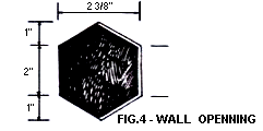
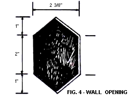
Centered approx. 30" above floor level cut an almost square opening 2 3/8" wide by 2" high in the wall directly above the 2 1/4" sole plate hole. Cut or file two 1" high triangular pieces above and below the almost square opening so that your wall opening exactly resembles. (Fig.4)
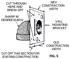
Now cut or break off " New Construction" section from metal wall mounting bracket and glue a sharp 90░elbow to the pre-riveted adaptor ring. (Fig.5)
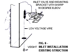
Insert top screw only through inlet valve and gently squeeze inlet valve stem into bracket assembly until you are able to just start top screw threads in bracket assembly hole. Strip the low volt wire and tape it to sharp 90░elbow with approx. 6" sticking through wire guide hole. Join to inlet valve wires with wire connectors supplied. Attach a small weight to the other end of low volt wire and drop weighted wire through opening in wall. Allow wire and weight to hang through sole plate. (Fig.6)
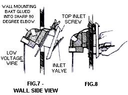
Insert assembled 90░sharp elbow and wall bracket assembly through wall cutout hole as illustrated.(Fig.7)
Once metal mounting bracket is completely inside wall cavity, side entire assembly upwards so metal plate is flush with inner wall surface and inlet valve is flush with outer wall surface. You can insert index finger through inlet valve opening and gently squeeze inlet valve stem further into inner wall assembly. (Fig.8)
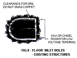
Note: Mount inlet valves so lid pulls down to open. Now insert and partially tighten bottom inlet valve screw. Tuck low voltage wires and connectors under sides of wall inlet valve. Adjust inlet valve for perfect vertical alignment and tighten both inlet valve-mounting screws. Be sure inlet valve lid operates freely. b. Floor Valves in Existing Structure To install a floor inlet, drill a pilot hole with a coat hanger and check the location as previously described. When you are sure that the proposed location will not be blocked by a joist or other obstruction, cut a hole in the carpet slightly larger that your 2 1/4 " drill bit. Drill a 2 1/4" hole in the floor. Chisel or saw this hole larger to accommodate the inlet valve low volt connections. (Fig.9)
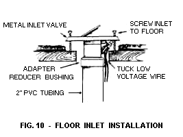
Assemble an adapter reducer bushing and some low volt wire to an inlet valve. Screw the valve to the floor. Repeat until all inlets are installed. (Fig.10)
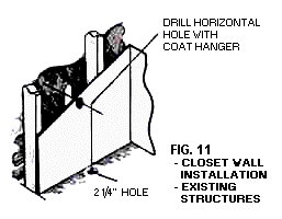
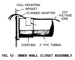
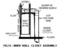
c. Closet Wall Installation - Existing Structure Often it is only practical to install your system with the line coming up through the floor inside a closet and then through both sides of the wall. To use this method, select suitable inlet valve location, exercising same precautions as for normal wall installation. Using a length of coat hanger, pierce a hole through both walls. (Fig.11)
Be sure to hold wire perfectly horizontal so that both interior and exterior holes line up with one another. Check for inner wall obstructions by bending short length of coat hanger wire at a right angle and twirling this right angle piece inside the wall. Drill a 2 1/4" hole horizontally through both sides of wall. Make the hole in the exterior wall surface into the same sharp opening as described previously in STEP 1 - (Installing Inlet Valves). (Fig.4)
From inside closet cut 2 1/4" hole through floor, either directly below opening in wall or convenient spot. (Caution: Make pilot hole as in STEP 1 previously.) Run low voltage wire through 2 1/4" hole in floor, and through wall to exterior of closet.
and tape low voltage wire to this assembly immediately behind the metal bracket. Attach wires to low voltage terminals at rear of inlet valve.
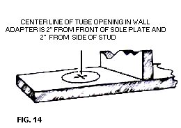
d. Wall Valve Installation - New Construction Select a probable location for inlet valve and drill a pilot hole in the floor. Go below to check that tubing path is clear of present, or future, obstructions such as floor joists, heating ducts, plumbing, wires, etc. At intended inlet valve locations, drill a 2 1/4" diameter hole through sole plate. To pinpoint center of hole measure over 2" from side of stud and 2" from front of sole plate. (Fig.14)
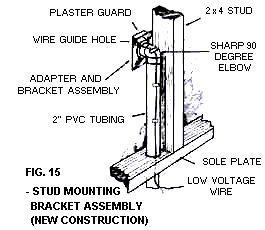
Glue a length of tubing into a stud Mounting Bracket Assembly. (Fig.15)
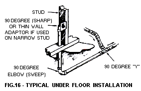
Cut a length of low voltage wiring; bring approximately 6" through top wire guide hole in stud bracket assembly and double it back into elbow hole. Tape wire to tubing at assembly elbow and again close to end, and tuck remaining wire into bottom of tubing. Screw plaster guard onto face of assembly. Drop bottom of tubing through 2 1/4" hole and nail stud Mounting Bracket Assembly to stud. Make sure center of inlet hole is at the correct height above floor level and tubing extends below sub-flooring. Go to STEP 2 installation of tube system and complete tubing system as much as possible. How to Install Your New Central Vacuum System STEP 2: Installation of Tube System (New or Existing Home) Starting at the inlet furthest from the power unit, temporarily fasten the main line in position. (Good idea: From a nail or overhead pipe, etc., make two loops of string or low voltage wire to pass PVC tubing through, to hold it in position while you work.) Push a length of PVC tubing up in it bottom of inlet valve assembly. Bear in mind, tube enters all fittings approximately 3/4". Measure, cut, and slip-fit this vertical line to main horizontal line with a 90-degree sweep elbow. Remove all inside burrs on end of tubing with pocketknife. Apply cement to both parts and assemble. Connect additional inlet valves to main truck line with the 90 degree "Y" assembly. (Fig.16)
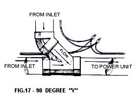
Be sure to install "Y" fittings so sweep is towards power unit. (Fig.17)
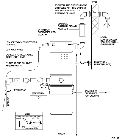
Always run branch lines, from sides or top of main trunk line, never out of the bottom as this will create a trap for dirt to fail into. Bring low voltage wire along as you assembly tubing. Join or splice wire with wire connectors at each branch or "Y" junction in the tubing. Neatly tape wire to tube. Proceed unit the tubing system is complete. STEP 3: Installation of Power Unit (Fig.18) The power unit is screwed to the wall with the bottom screws of the mounting bracket about 48" up from the floor to allow convenient removal of the dirt canister. For proper motor cooling there must be at least 8" between the unit and the ceiling. If mounting on plaster or panel walls, were sure mounting bolts enter studs. If mounting on concrete wall, drill the wall with masonry bit and insert plastic or lead anchors. As an alternate mounting on concrete walls, 2" x 4" studs or plywood may be suspended from overhead. With the power unit mounted, strip the low voltage wire and remove the two silver colour "Quick Connect" or "slip-on" terminals from Control Panel with a pair of pliers and insert the wire into the "Quick Connect" terminals and crimp and insert the silver terminals back into place. Note: There are no polarity requirements.
Connect main 2" tubing line to the Intake Assembly on Power Unit. (some Power Units have the optional left or right side Intake). Do not cement this connection to power unit for service and in case you wish to remove at some future date. The unit may be exhausted to exterior to expel odour, fine dust, germs, and some noise. To reduce noise you could add the optional exhaust muffler. Use same standard pipe and fittings as before. Note: On/Off switch on power unit is for the Utility Valve on power unit or for troubleshooting only. All other inlets operate automatically when hose end is inserted into inlet valve, and with switched hoses the switch turned to On position.
WARNING: Electric Shock Could Occur if Used On Wet Surfaces. | |
 top
top