For Household Use Only. Install only on a normal ~120V, 60Hz, 7A supply protected by a maximum 15A over-current protective device. The pin connector on this type of wall valve is intended for use on a normal ~120V, 60Hz, 7A supply only. It is required to be wired by a qualified electrician and is required to conform to local electrical codes.
Warning: To reduce risk of fire and electric shock, connect only Allegro Super Deluxe "Direct Connect" electric hose ZAS090DC or ZAS090DC-35. Do not operate hoses on wet surfaces.
NEW CONSTRUCTION
1. Install Building Wire Constructors (1) through the approved type electrical Connector(2) (supplied) until they produce approximately six inches from connector. Seat connector firmly into the opening atop the WIRING COMPARTMENT (4). Insert and secure LOCKING TAB (3).
2. Splice wires from INLET VALVE RECEPTACLE (7) to the protruding building wire conductors with #31 TWIST-ON WIRE CONNECTORS (8) (not supplied). Note: White wire to the white wire & black wire to black wire.
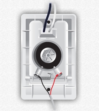
Feed LOW VOLTAGE RELAY WIRES (5) ZIC020 through opening in the LVT COVER PLATE(6) and connect to the two contact screws of INLET VALVE FACE PLATE (9).
Push Inlet Valve face plate (10) into MOUNTING PLATE (11). At the same time, push ELECTRICAL CONDUCTORS (12) and connectors (8) into WIRING COMPARTMENT(4). Back out the two screws that hold the wiring compartment in place. Slip upper a finished-wall clip (13) with MOUNTING SCREWS (supplied).
Install the lower FINISHED WALL CLIP (14) with screws (supplied).
Secure Inlet Valve face plate (10) ZIC011-W to mounting plate (11) using the two supplied colour matched SCREWS (15).
EXISTING CONSTRUCTION
After pipe, low-voltage relay control wire, electrical building wires and opening in wall has been cut:
Remove mounting plate NAILING FLANGE (16). Use a hacksaw or score with razor knife along the dotted line and snap off.
Repeat step one (from New CONSTRUCTION).
Install modified mounting plate with short 90° elbow ZIC018 glued in position into wall opening.